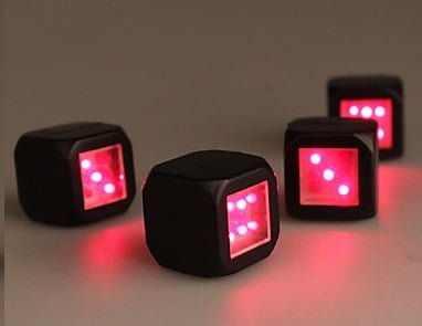
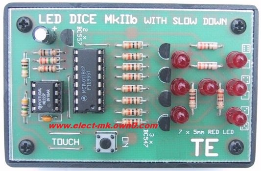
You can make yourself an Electronic Dice that works just like a dice in a game giving random number whenever you press the button. It can be used in games and for children who dont know how to roll the dice or also for handicapped persons.
It is a simple and classic project for those getting interested in electronics. A timer, counter and a few LEDs makes a circuit that can also add a new twist to some old boring board games.
It is a tested and 100% working circuit. Circuit testing and images credits goes to Muhammad Bilal (Hamdard University).
Components Required:
- NE555 IC
- 4017B IC
- 6x 1N4148 Diode
- 7x Red LEDs
- 4x BC109 Transistor
- 7x 1 Kohm Resistor
- 5x 10 Kohm Resistor
- 2x 2.2 Kohm Resistor
- 100 Kohm Resistor
- 22 uF Capacitor
- 0.01 uF Capacitor
- Push Switch Button
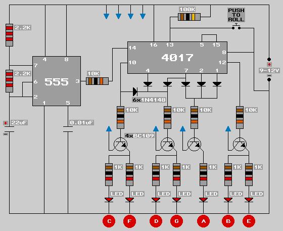
Circuit Diagram:
Connect all the arrows ![]() on the transistors to the positive supply rail.
on the transistors to the positive supply rail.
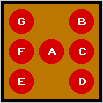
The LEDs Should Be Alligned As Following Image
Working:
The 555 timer IC is connected for Astable Operation, the clock pulses are fed to the 4017 IC via the 10K resistor. The 4017 is a 10 stage counter, output 6 (pin 5) is connected to RESET (pin 15), thus giving us a 6 stage counter , outputs 0 to 5.
6 of the LEDs are connected as 3 pairs, thus requiring 4 different signals, these signals come from the 4 transistors, which in turn are connected to the nescessary outputs of the 4017. Where a transistor is operated from more than one output, diodes are used to avoid a short circuit situation between outputs.
Pin 13 of the 4017 (INHIBIT) is connected to +ve via a 100K resistor to stop the counter from advancing, however pressing the ROLL button will connect pin 13 to -ve and allow the counter to advance, hence, throwing the dice.


